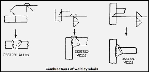
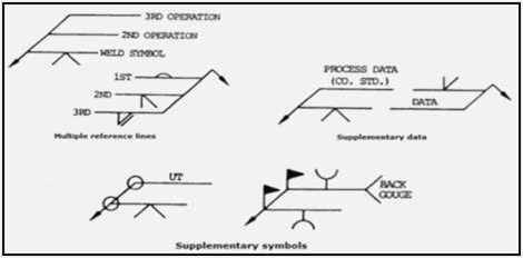
1.1. Location of the Weld with Respect to Joint:
a.Arrow Side. Welds on the arrow side of the joint are shown by placing the weld symbols on the side of the reference line toward the reader.

b.No Side Significance. Resistance spot, resistance seam, flash, weld symbols have no arrow side or other side significance in themselves, although supplementary symbols used in conjunction with these symbols may have such significance.
See the example below, the flush contour symbol is used in conjunction with the spot and seam symbols to show that the exposed surface of one member of the joint is to be flush. Resistance spot, resistance seam, flash, and upset weld symbols shall be centered on the reference line.

c.General Notes. General notes similar to the following may be placed on a drawing to provide detailed information to predominant welds. This information needs not be repeated on the symbols:
- “Unless otherwise indicated, all fillet welds are 5/16 size.”
- “Unless otherwise indicated, root openings for all groove welds are 3/16 in. size”.
1.2. Use of Inch, Degree and Pound Marks:
a. Inch marks are used for indicating the diameter of arc spot, resistance spot, and circular projection welds, and the width of arc seam and resistance seam welds when such welds are specified by decimal dimensions. In general, inch, degree, and pound marks may be used on Welding Symbols, as desired.

b. In a bevel or J-groove weld symbol, the arrow shall point with a definite break toward the member which is to be chamfered. In cases where the member to be chamfered is obvious, the break in the arrow may be omitted.

c.Information on Welding Symbols shall be placed to read from left to right along the reference line in accordance with the usual conventions of drafting.

d.For joints having more than one weld, a symbol shall be shown for each weld.

e.The letters CP in the tail of the arrow indicate a complete penetration weld regardless of the type of weld or joint preparation.

f. When the basic weld symbols are inadequate to indicate the desired weld, the weld shall be shown by a cross section, detail, or other data with a reference to the Welding Symbols according to location specifications.

g.Two or more reference lines may be used to indicate a sequence of operations. The first operation must be shown on the reference line nearest the The field weld symbol may also be used in this manner.

we provide standard specifications for welding procedures for all NDT Welding process and Brazing. We offer Welder Procedure Specification, Welder Certificate Renewal Process, Procedure Qualification Record, Welder Qualification Testing, welder Training and Welder qualification services in Coimbatore, Trichy, Salem, Erode, Chennai.
References:
1. AQC Inspection


